Engine
Rolls-Royce/Snecma Olympus 593
Rolls-Royce (Bristol Siddeley until 1966) and SnecmaUnited Kingdom and France
- Type
- Two-spool turbojet with partial reheat
- Introduced
- 1976
169.2kN
Peak thrust
Figures for the Olympus 593 Mk 610, the production Concorde engine (Jane's figures)
General
- Type
- Two-spool turbojet with partial reheat
- Status
- Retired
Programme
- Introduced
- 1976
Architecture
- Configuration
- Two-spool axial turbojet: 7-stage low-pressure and 7-stage high-pressure compressors, each driven by a single-stage turbine; annular combustion chamber with 16 vaporising burners; partial reheat; diameter 1,212 mm
Induction and fuel
- Fuel system
- Engine fuel control with a separate reheat system; intake ramps scheduled by digital Air Intake Control Units
- Fuel
- Jet A-1
Weight and size
- Dry weight
- 7,000 lb
- Length
- 159.02 in
Performance
- Thrust
- 169.2 kN
- Overall pressure ratio
- 15.5:1


The Olympus 593 was the engine of Concorde: a two-spool turbojet with reheat, built jointly in Britain and France, that carried the only supersonic airliner in sustained commercial service from 1976 to 2003. Four of them hung in pairs beneath the delta wing, each inside a nacelle that was as much part of the engine as the compressors: a variable intake at the front, a variable nozzle at the back, and a set of control computers deciding, second by second, how the three should work together.
It was not a new design. The 593 descended from the Bristol Olympus that powered the Avro Vulcan bomber and, more directly, from the reheated Olympus 320 developed for the BAC TSR-2 strike aircraft. The civil programme began as a partnership between Bristol Siddeley Engines and the French engine maker Snecma; when Rolls-Royce bought Bristol Siddeley in 1966, the badge on the nacelle changed, but the work-share between Filton and the Paris region did not.

What made the engine remarkable was not its size or its thrust, which were modest by the standards of the wide-body turbofans that arrived in the same decade, but the regime it was built for. Concorde cruised at twice the speed of sound for hours at a time, and the Olympus was designed to run continuously there, without reheat, with air arriving at the compressor face already hot from being slowed down in the intake. At that condition the complete powerplant reached an overall efficiency of about 43 per cent, an exceptional figure for any heat engine of its time.
The same choices that made it efficient at Mach 2 made it loud and thirsty at low speed. A pure turbojet with a narrow cross-section was the right answer for supersonic cruise and the wrong one for airport neighbours, and noise followed Concorde throughout its career. Twenty-seven years of service ended with the retirement of the Air France and British Airways fleets in 2003, and the Olympus 593 has had no successor.
Aircraft fitted with this engine
Year each aircraft entered service with this engine.
- 1976593-22R (prototypes); Mk 610-14-28 (production)
Concorde
The only aircraft to use the engine in service, 1976 to 2003.
- Olympus 593 in a ventral nacelle
Avro Vulcan (flying test bed)
Flight-tested the engine and nacelle up to Mach 0.98 before Concorde flew.
2 aircraft
Development
 Olympus Mk 101
The Olympus began as a bomber engine. In the late 1940s the Bristol Aeroplane Company proposed a jet bomber to the specification that eventually produced the Vulcan and the Victor, and its engine division designed a new turbojet for it, the B.E.10. The bomber was not built, but the engine's two-spool layout: a low-pressure and a high-pressure compressor, each on its own shaft and driven by its own turbine: kept the Air Ministry interested. The first engine ran on 16 May 1950 under Stanley Hooker, Bristol's new chief engineer, and delivered 10,000 lbf on its first acceleration to full power.
The Olympus entered service in the Avro Vulcan, first as the Mk 101 and then, redesigned for much more thrust, as the 200 series. A Canberra fitted with early Olympus engines set world altitude records in 1953 and 1955. The 300 series added a compressor stage for more airflow, and in 1962 Bristol Siddeley, formed when Bristol's engine business merged with Armstrong Siddeley in 1959, won the contract to power the TSR-2 with the Olympus 22R, known to the RAF as the Mk 320. It was rated at 19,610 lbf dry and 30,610 lbf with reheat, and it was designed for sustained flight at Mach 2.2.
 Olympus 320
That last requirement made it the obvious starting point for a supersonic airliner. The engineers planning Concorde studied turbofans as well as turbojets, but a turbofan's larger frontal area meant more drag at Mach 2, and a transatlantic supersonic aircraft lived or died by its cruise efficiency. Rolls-Royce proposed an all-new engine, the RB.169, but developing a clean-sheet design for a single aircraft would have been very costly, while the Olympus 320 already existed and was running in the TSR-2 programme. A civil derivative was drawn up as the Olympus 591, then reworked into the 593, whose specification was settled on 1 January 1964.
The TSR-2 itself was cancelled in 1965, leaving Concorde as the Olympus's only supersonic future. The choice of a turbojet was later vindicated by the Soviet competitor: the Tupolev Tu-144 first flew with reheated turbofans and needed reheat in cruise, and its later engine was a non-reheated turbojet that improved its performance considerably.
Design

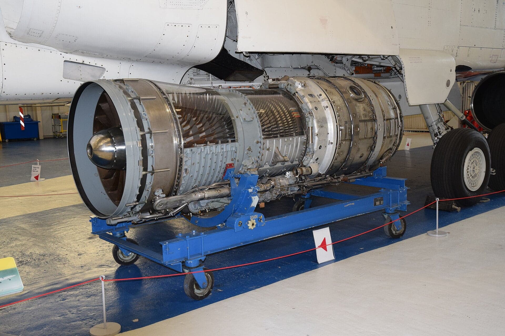
Mechanically, the Olympus 593 kept the layout the Olympus had had since 1950. Air passed through a seven-stage low-pressure compressor and a seven-stage high-pressure compressor, each on its own shaft and each driven by a single-stage turbine. Between them sat an annular combustion chamber of nickel alloy, fed by sixteen vaporising burners with twin outlets. In the production Mk 610, the whole engine was about 13.3 ft long and 3.97 ft in diameter, and weighed around 7,000 lb dry.
What changed was the temperature. A subsonic airliner's compressor takes in cold air from high altitude; Concorde's took in air that had already been slowed from twice the speed of sound in the intake, and at Mach 2 cruise it reached the engine face at more than 120 °C. By the time it had been squeezed through the compressor it was hot enough that the usual materials would not do. The compressor drums and blades were titanium, but the last four stages of the high-pressure compressor were made of Nimonic 90, a nickel alloy normally found only in the turbine.

The turbine itself was cooled: the high-pressure turbine's stator and rotor blades and the low-pressure turbine's rotor blades all had internal cooling, which let the metal survive in a gas stream far hotter than the compressor. Behind the last turbine stage, straightening vanes turned the flow before it entered the reheat jet pipe.
On the ground, the engine's own pressure ratio was about 15.5 to 1, and it swallowed around 410 lb of air a second. At cruise the engine's compressors contributed less: about 11.3 to 1, because the air arriving was already hot: but the intake in front of them added a pressure rise of its own, and together they gave the whole powerplant an overall pressure ratio of about 82 to 1.
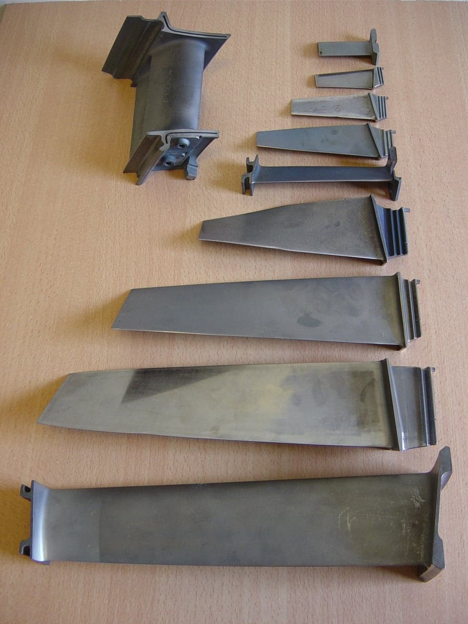
The engine was designed for airline life. Its major components had a design life of 25,000 hours, with compressor and turbine blades at 10,000 hours; the primary exhaust nozzle and jet pipe were designed for 30,000 hours and the rear thrust-reverser structure for 40,000. An installed engine could be removed and replaced on the aircraft in 1 hour 50 minutes.
Fuel and carburation
Every turbojet trades noise and low-speed economy for a narrow, fast jet, and the Olympus 593 made that trade more completely than any other airliner engine of its day. Jane's figures for the Mk 610 give a specific fuel consumption of 1.195 lb of fuel per pound of thrust per hour in supersonic cruise, rising to 1.39 at sea level. For the complete aircraft at Mach 2 and 60,000 ft, that meant a consumption of about 4,800 US gal an hour.
In cruise, that fuel bought speed, and the efficiency of the whole powerplant at Mach 2 was excellent. Measured per passenger, however, Concorde could not compete with the wide-bodies. With a full load it achieved about 15.8 passenger-miles per US gallon, against 33.3 for a Boeing 707, 46.4 for a Boeing 747 and 53.6 for a McDonnell Douglas DC-10. When the 1973 oil crisis arrived, just as airlines were deciding whether to take up their Concorde options, that comparison weighed heavily against the aircraft.
Noise was the more public problem, and it had two separate sources. The sonic boom was a consequence of flying supersonically at all, and it confined Concorde to supersonic flight over the sea; several countries, the United States among them, refused supersonic overflight. Airfield noise came from the engines, and it was the one issue that development testing never fully resolved. Snecma made genuine advances in silencer design during the programme, but by 1974 the spade-type silencers projecting into the exhaust were reported to be ineffective, though the aircraft entering service were still expected to meet their noise guarantees.
The fight over landing rights in New York made Concorde a symbol in a wider argument about aircraft noise, and it led directly to a general noise-abatement programme at John F. Kennedy Airport. In practice many observers found the aircraft quieter than they had feared, partly because pilots throttled back briefly while crossing residential areas. The lasting fix (an engine without reheat and with a slower, quieter jet) was the Mk 622, and it was never built.
Production
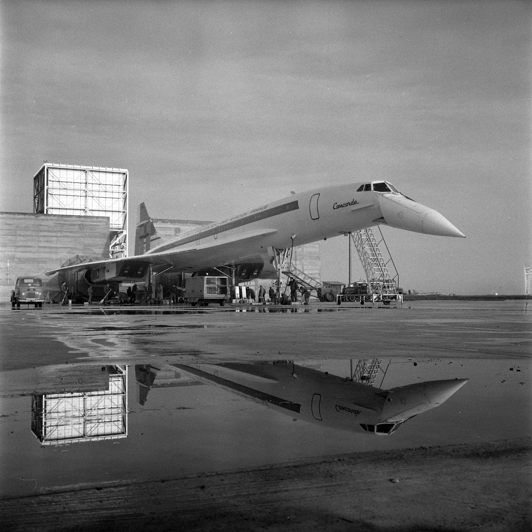
Concorde was built under a treaty, not a contract. The British and French governments signed the agreement on 29 November 1962, at a time when Britain was pressing to join the European Economic Community, and at British insistence it carried heavy penalties for whichever side withdrew. Airframe and engine were divided between the two countries from the start, and the division was political as much as industrial: because France took the larger share of the airframe, Britain took the larger share of the powerplant.
On the engine side, Bristol Siddeley was responsible for the Olympus itself and its accessories. Snecma, the French state engine maker, took the exhaust system: the variable nozzle, the thrust reverser, the noise-attenuation work and the reheat, which was not in the original plan at all. The British Aircraft Corporation, Concorde's British airframe partner, designed the variable intake and the overall engine installation. The same two engine companies were working together at the time on a smaller, unrelated turbofan, the M45H.

Testing was spread across both countries. Bristol Siddeley ran engines at Patchway, next to the Filton works; the National Gas Turbine Establishment at Pyestock provided test cells; and in France the Centre d'Essais des Propulseurs at Saclay ran the engine in its altitude chambers, while Snecma's plant at Melun-Villaroche ran the first complete engine with its exhaust system.
In 1966 Rolls-Royce bought Bristol Siddeley and turned it into its Bristol Engine Division. The engine's name followed the change: the Bristol Siddeley to Snecma Olympus became the Rolls-Royce/Snecma Olympus 593: but the team, the site and the programme stayed where they were. Some nacelle plates still carried the older wording, pairing the Rolls-Royce badge with the Bristol-Snecma name.
In service

The Olympus 593 carried Concorde into the air for the first time on 2 March 1969, when prototype 001 took off from Toulouse with André Turcat, Sud Aviation's chief test pilot, in command. Using reheat, it lifted off at 205 kt after a ground run of about 0.8 nm. The engine runs that preceded that flight included runs of 001 on the runway at Blagnac in December 1968.
Seven years of flight testing and certification followed. Most of the powerplant's early problems: surging during manoeuvres at Mach 2, the interaction between neighbouring engines, the scheduling of intake and engine together: were worked out through changes to hardware and to the intake and engine control laws. Airfield noise remained the exception.

Concorde entered scheduled service with Air France and British Airways on 21 January 1976, from Paris and London respectively. Over the following years the airlines flew it to New York, Washington, Rio de Janeiro, Caracas, Bahrain, Miami and Barbados, among other destinations, and British Airways eventually made the service profitable by positioning it as a premium product.
In airline hands the Olympus was a mature engine, not an experiment. Its design lives were long for a supersonic powerplant, and the ability to change an engine on the aircraft in under two hours mattered to fleets of only a handful of aircraft each, where a single grounded airframe was a large share of the schedule.
The fleet never grew. Only Air France and British Airways took delivery, and the Olympus 593 remained an engine for one aircraft type, flown by two airlines, for its entire commercial life.
Reliability and maintenance

On 25 July 2000, Air France Concorde F-BTSC crashed at Gonesse shortly after taking off from Paris-Charles de Gaulle. All 109 people on board and four people on the ground were killed. The investigation was led by France's Bureau d'Enquêtes et d'Analyses (BEA) with the participation of the British Air Accidents Investigation Branch, and the engines figure prominently in its account, as victims of the event, not its cause.
During the take-off run, after V1, a tyre on the left main landing gear ran over a metal strip that had fallen from a DC-10 which had departed five minutes earlier. The tyre was destroyed, and the BEA concluded that the impact of a piece of tyre caused a large section of fuel tank 5 to rupture. The leaking fuel ignited, and a large fire developed under the left wing.
The two left-hand engines were directly behind that fire. According to the BEA, engines 1 and 2 surged at the same moment, with a slight loss of thrust on engine 1 and a severe loss on engine 2; the report attributes engine 1's surge probably to ingestion of hot gases or solid debris, most likely pieces of tyre, and engine 2's to ingestion of hot gases from the fire. Engine 1 recovered almost to nominal thrust, then surged again at lift-off, as did engine 2. The engine 2 fire alarm sounded, the flight engineer announced the shutdown, the throttle was brought to idle and the fire handle pulled.
With the landing gear failing to retract and a thrust deficit, the aircraft could neither climb nor accelerate. A third surge, caused by ingestion of structural debris, hot gases and/or fuel, left engine 1 with a definitive loss of thrust; the loss of thrust on engines 3 and 4 that followed resulted from the crew's deliberate reduction to idle combined with surges caused by distorted airflow. The BEA also found that a spacer had not been refitted on the left main gear bogie during maintenance, and concluded that this omission did not contribute to the accident. It stated that even with engines operating normally, the severe fire damage would rapidly have led to the loss of the aircraft.
The probable causes the BEA gives are the tyre's destruction by the metal strip, the rupture of the tank, and the ignition of the leaking fuel, by an electrical arc in the landing-gear bay or by contact with hot engine parts, producing a very large fire and major thrust losses on engines 2 and then 1. Concorde returned to service in November 2001 after modifications to the aircraft.
Upgrades

The first engines built for the programme were two Olympus 593D units, completed in July 1964. The D stood for “derivative”: they were close relatives of the TSR-2 engine, built to prove the ideas the civil engine depended on, above all the cooling of the turbine stator and rotor blades and running at sustained high temperature. They did that, and they also showed that the engine was too small. Concorde had grown since the 593D was sized for it.
The answer was the 593B, B for “big”, which first ran in November 1965. It was a redesign, informed by the D's test results, and the letter was eventually dropped from the name. In parallel, Snecma tested scale models of the exhaust system using an Olympus 301, and in June 1966 the first complete Olympus 593 with its variable-geometry exhaust ran at Melun-Villaroche. The engine went into the altitude chamber at Saclay for the first time in April 1967.
Aircraft weight kept rising through the design phase, and by the time the numbers were settled the take-off thrust Concorde needed was about 20 per cent more than the dry engine could give. Rather than start again, the team added partial reheat, developed by Snecma. It was never meant to be an afterburner in the military sense of a large, fuel-hungry boost; it was a modest increment for take-off and for pushing through the transonic region, and the aircraft cruised without it.
The engine flew long before Concorde did. At Bristol, an RAF Avro Vulcan was converted into a flying test bed with a complete Olympus 593 and its nacelle slung beneath the bomb bay. The Vulcan could not exceed Mach 0.98, so the supersonic end of the envelope stayed on the ground, but in those tests the 593 delivered 35,190 lbf, beyond its specification. By January 1968 the Vulcan had logged 100 flying hours, and the exhaust assembly had been cleared at Melun-Villaroche for flight in the Concorde prototypes.
 Olympus 593-602B
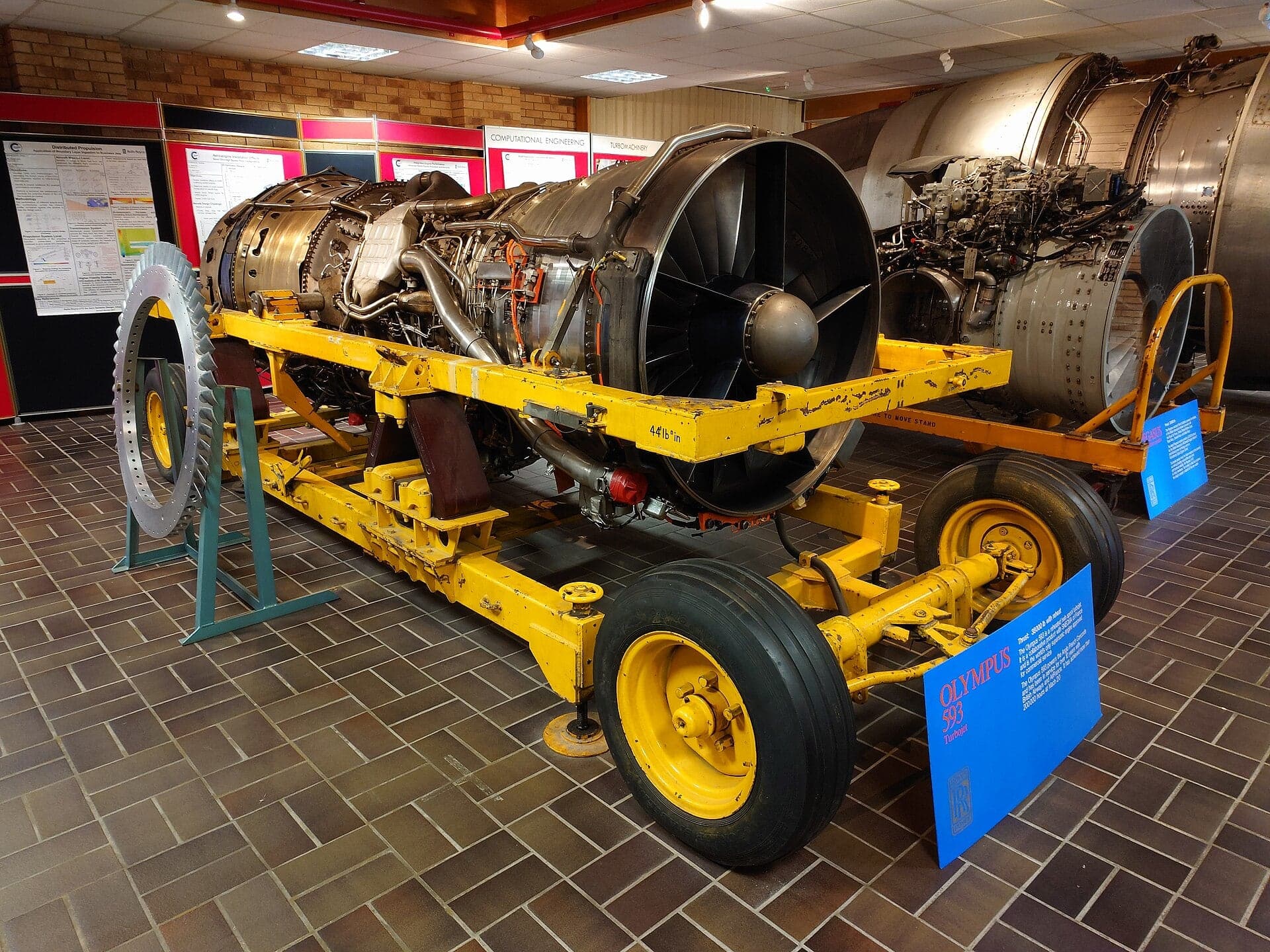
The prototypes flew with the Olympus 593-22R; the Science Museum in London holds a Mark 3B engine, serial 59351, built by Rolls-Royce in Derby around 1969 and taken from the British prototype, Concorde 002. Production aircraft received the Mk 610, whose final build standard, the 593-610-14-28, is the engine the airlines flew for twenty-seven years. Intermediate standards such as the 593-602 bridged the two; one 602B survives at Cranfield University.
A further mark never went beyond proposal. The Mk 622 was to be quieter and more powerful, dispensing with reheat and lowering jet velocity to cut noise, with enough extra efficiency to open routes across the Pacific and across the United States. It was part of the proposed Concorde “B”, and it died with the aircraft's order book.
Records
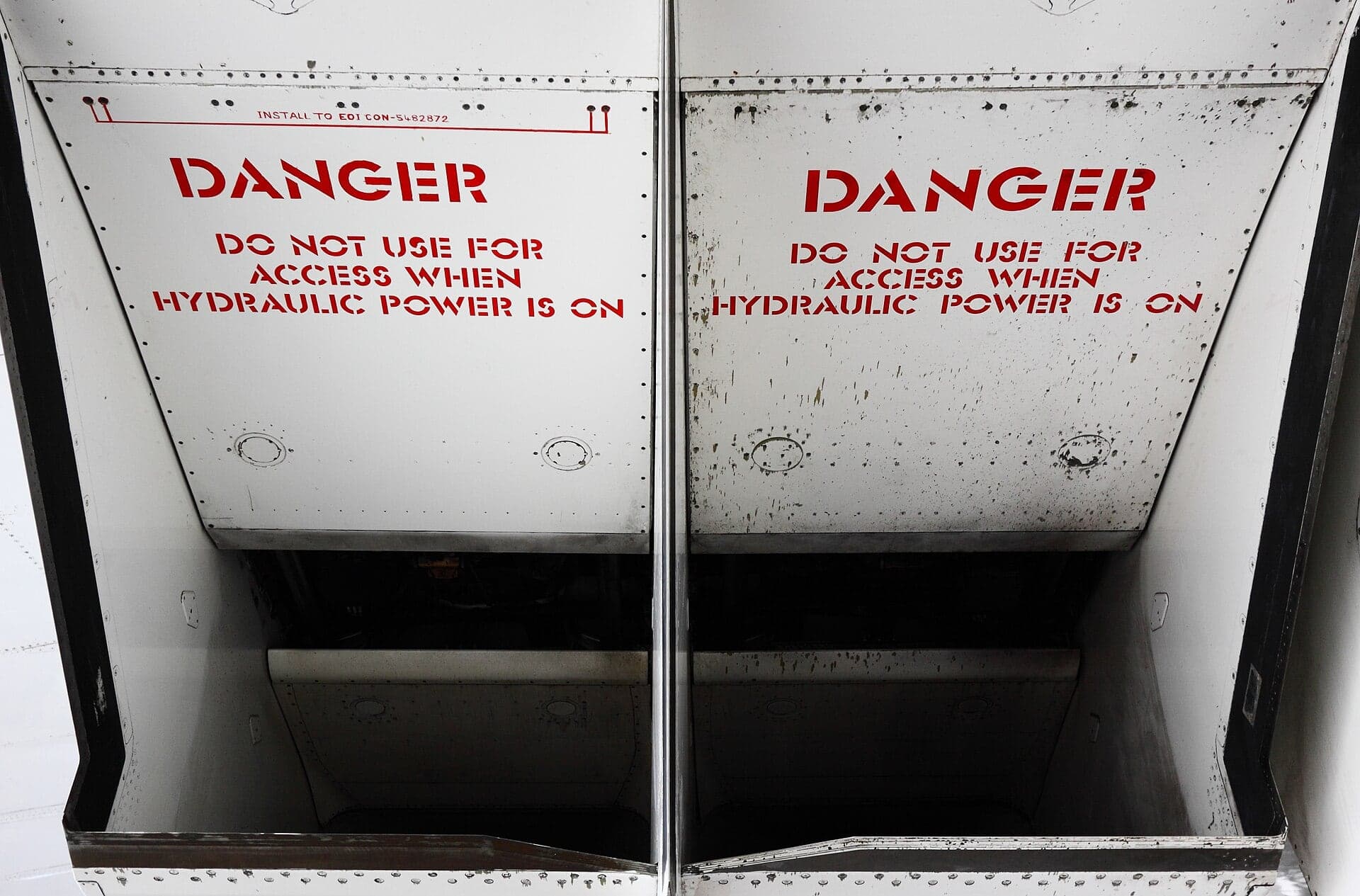
Concorde was a supercruiser in the literal sense: it flew supersonically for hours without reheat. The reheat was lit for take-off and again for the transonic push, from about Mach 0.95 to Mach 1.7; above that the dry engines were enough, and the aircraft settled into its cruise at Mach 2.02. What made that possible was less the Olympus on its own than the system it sat in, and the numbers show how far the credit was shared. At cruise, the engine's own thrust, transmitted through its mounts, was only about 8 per cent of the propulsion system's total. Around 63 per cent came from forward pressure on the internal surfaces of the intake, and most of the remainder from forward pressure on the exhaust nozzle.
The intake, designed by the British Aircraft Corporation, had to deliver air to the compressor at as high a pressure as possible and as evenly as possible, at every speed from a standstill to Mach 2. At supersonic speed, hinged ramps in the roof of the rectangular duct turned the flow and generated a system of oblique shock waves, slowing the air in steps rather than in one lossy jump. A slot in the ramp bled off the thickened boundary layer and passed it around the engine; dump doors spilled excess air when the engine was throttled back; and, because an intake sized for cruise was too small for take-off, an auxiliary inlet door opened to feed the engine at low speed. At Mach 2 cruise the intake alone raised the pressure by a ratio of about 7.3 to 1.

Keeping all of that correct was a control problem as much as an aerodynamic one. The powerplant had to tolerate pushovers, sideslips, pull-ups and slammed throttles at Mach 2 without surging, and adjacent powerplants interacted so strongly above Mach 1.6 that Concorde had to be certified aerodynamically as a twin-engined aircraft above that speed. Analogue control was not precise enough, and around 1972, late in the programme, BAC's Electronics and Space Systems division at Filton developed digital Air Intake Control Units to position the ramps and spill doors. They also scheduled engine speed to preserve surge margin, and they were connected to sensors near the nose, some 190 ft away, by multiplexed serial data links, an early use of digital data highways in an airliner, and a considerable saving in wiring and pneumatic piping.
At the back, the engine's own variable primary nozzle discharged into a secondary nozzle mounted on the airframe and developed by Snecma. Its two “eyelids” moved with the flight regime. In the cruise they opened fully, and together with the primary nozzle they formed an ejector: the engine jet pumped the secondary air bled from the intake through a divergent passage, and the expansion pushed forward on the nozzle walls.
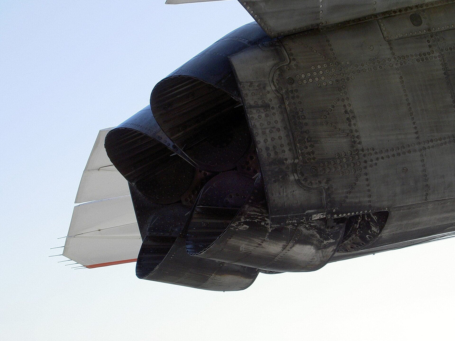
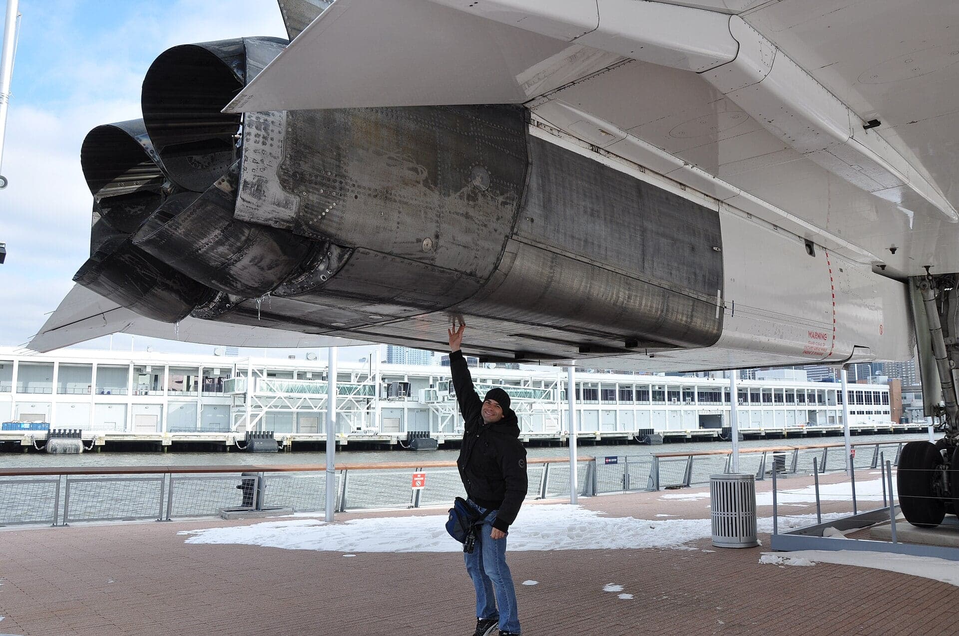
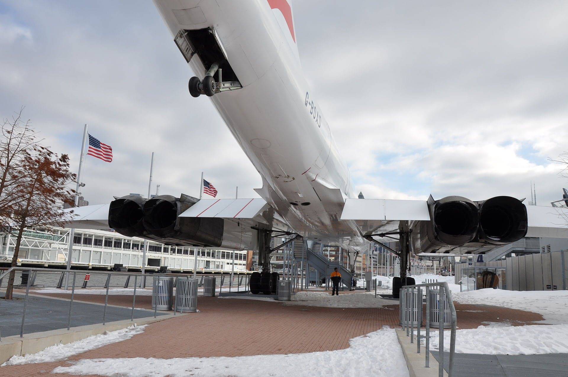
Closed into the jet, the same eyelids became the thrust reverser, deflecting the exhaust forward to help slow the aircraft after landing. One set of moving parts served as a supersonic expansion nozzle, a subsonic ejector and a reverser, and the rear of each nacelle, visible on every preserved Concorde, is that mechanism at rest.
Preservation
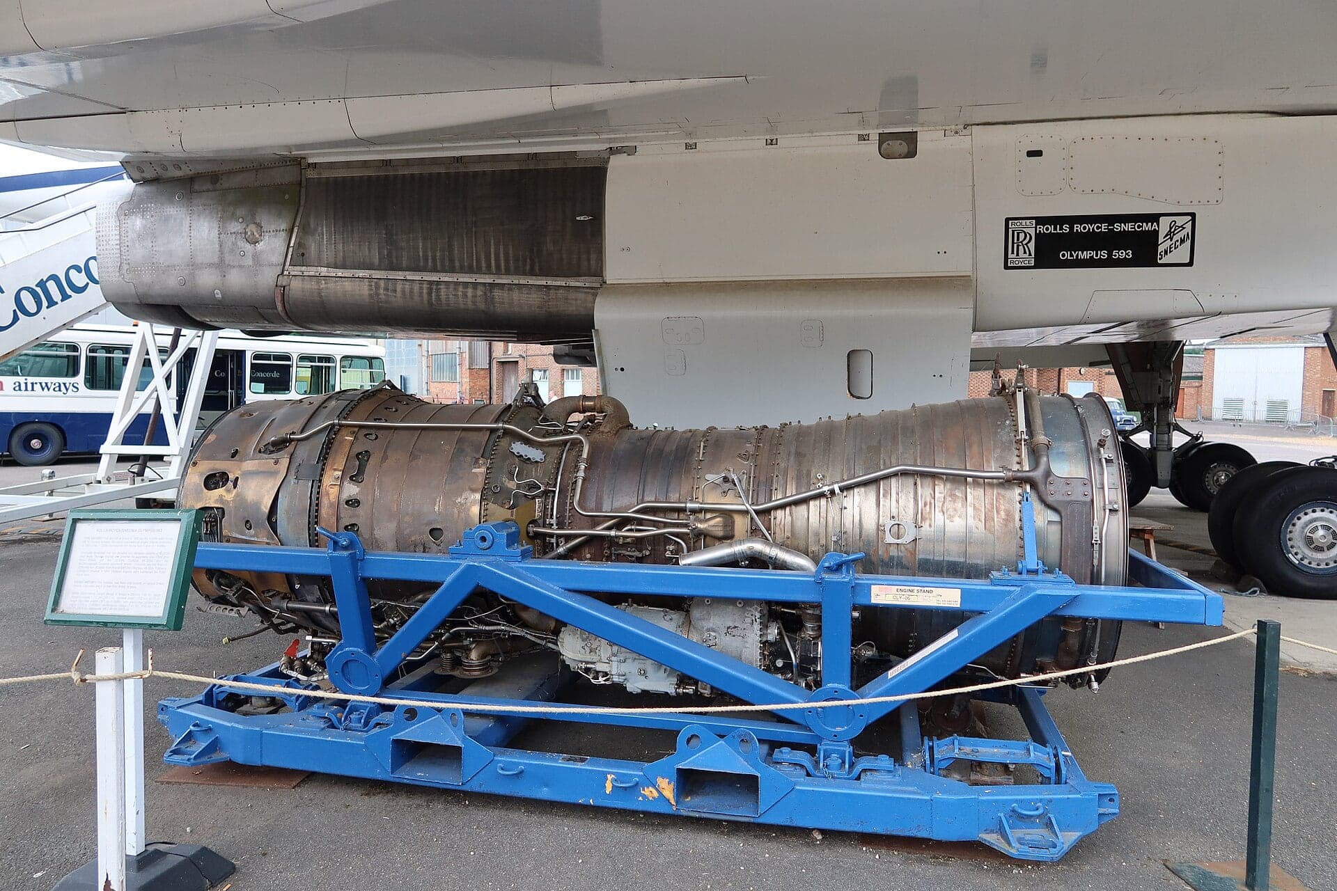
Because Concorde was preserved almost in its entirety, nearly every surviving airframe went to a museum, the Olympus 593 is one of the most widely exhibited jet engines in the world, both inside the nacelles of preserved aircraft and as separate exhibits.
In Britain, examples stand beside or beneath Concordes at Brooklands Museum in Surrey, next to G-BBDG, and at Aerospace Bristol in Filton, home of G-BOAF, the last Concorde to fly.
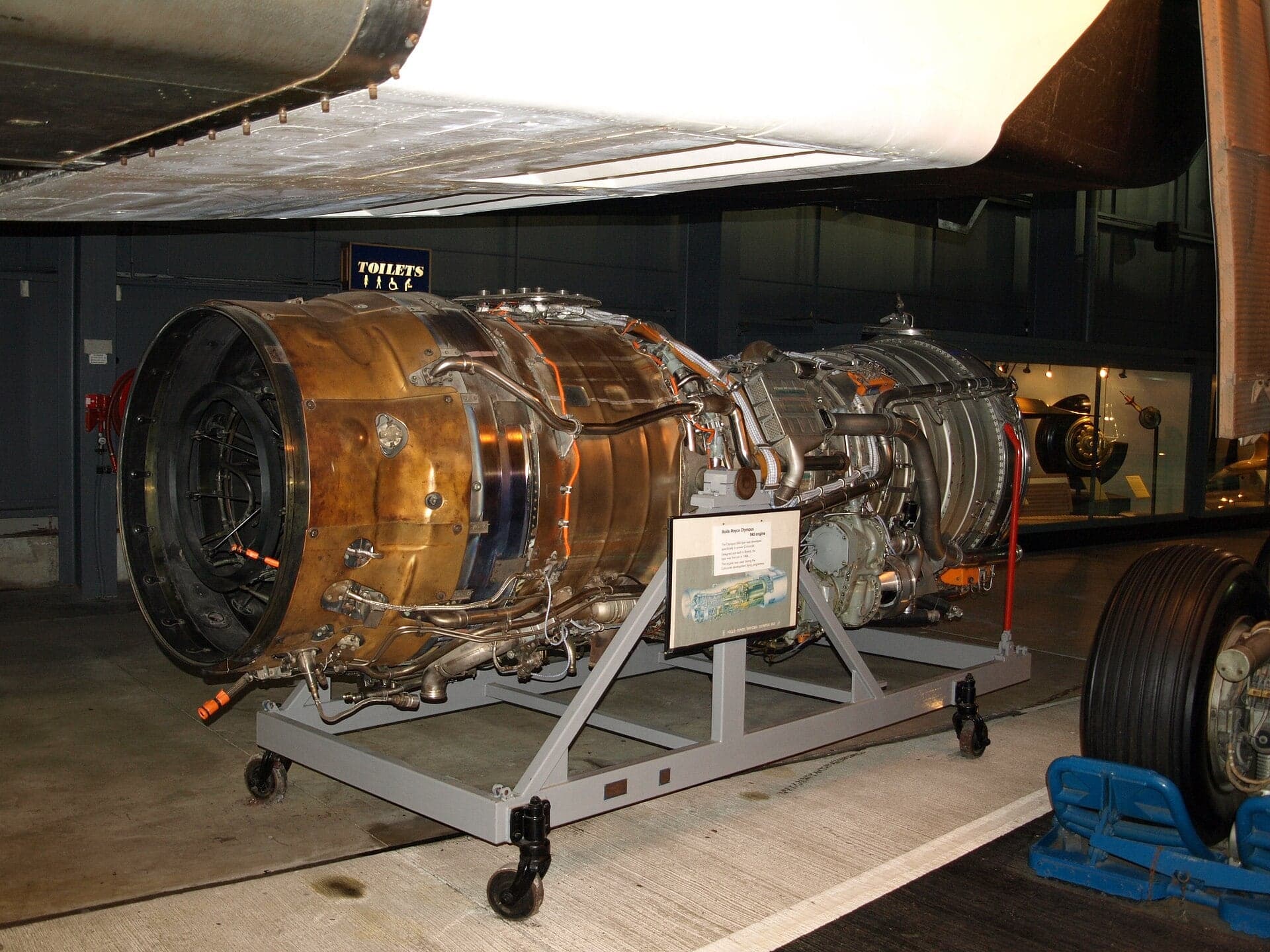
The Fleet Air Arm Museum at Yeovilton displays one under the wing of the British prototype, Concorde 002. Others are shown at the National Museum of Flight at East Fortune in Scotland, at Newark Air Museum and at the RAF Museum Cosford, while Cranfield University keeps a 593-602B in its Whittle Building.
The Science Museum in London holds engine 59351, a Mark 3B from Concorde 002, which entered its collection in 1977.
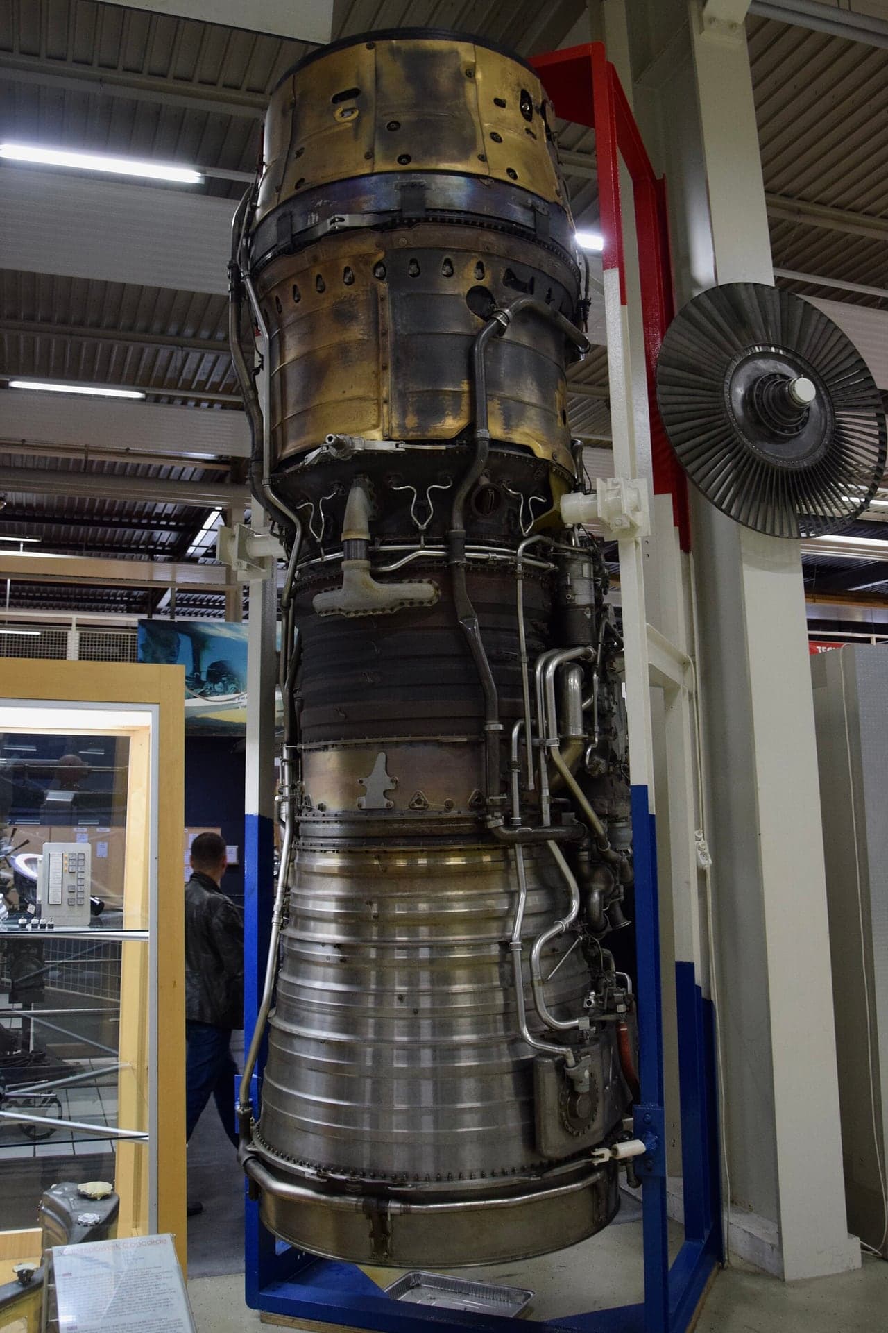
In France, Safran's own heritage museum shows the engine alongside the company's other products, and the aviation museum at Corbas, near Lyon, displays two examples that came from the air base at Romorantin. Outside Britain and France, the Technik Museum Sinsheim in Germany, which also exhibits Air France Concorde F-BVFB, displays an engine stood on end with its reheat section fitted.
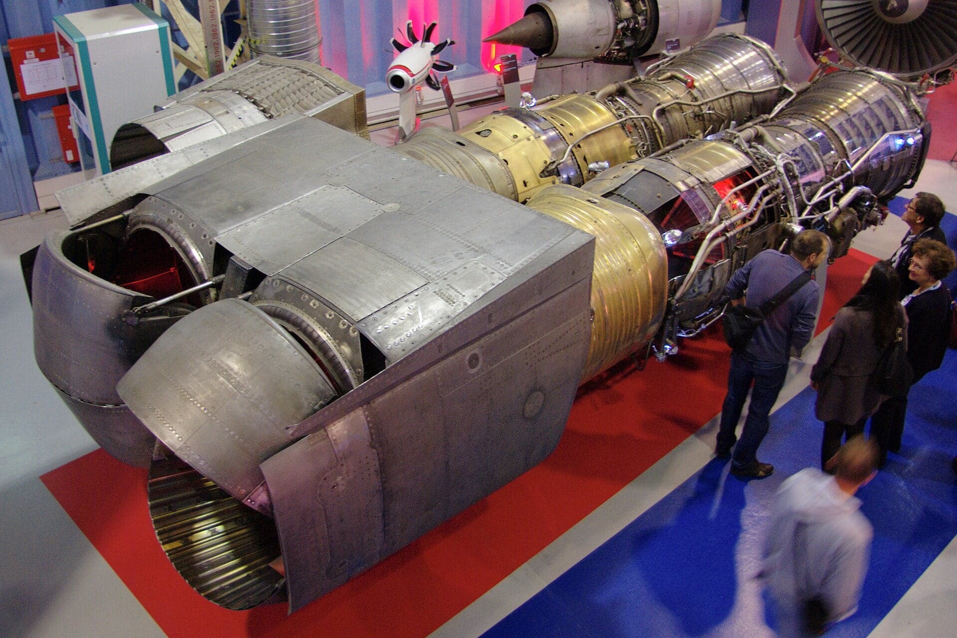
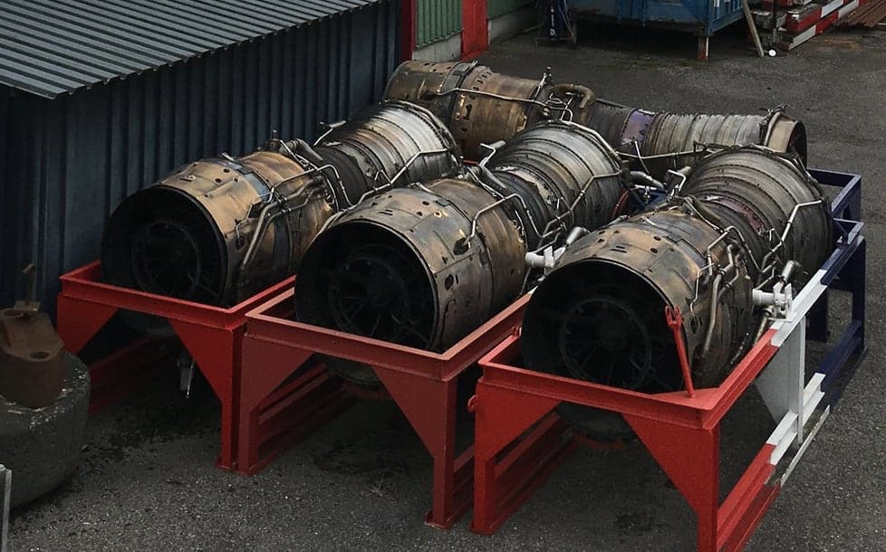
Sinsheim also holds the four Olympus 593s removed from F-BVFB itself, arranged side by side on stands. In the United States, an example is shown beside G-BOAD at the Intrepid Museum in New York, and engines are on display at the Georgia Institute of Technology and at the University of Illinois at Urbana-Champaign.
The nacelles of the preserved aircraft tell the rest of the story: the intake ramps, the auxiliary doors and the eyelid nozzles can still be seen on Concordes at Le Bourget, Duxford, Seattle, the Udvar-Hazy Center and elsewhere.
Legacy
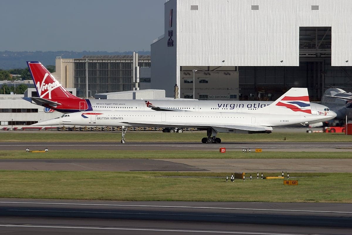
The return to service in November 2001 did not restore Concorde's economics. On 10 April 2003, Air France and British Airways both announced that they would retire the aircraft, citing falling revenue and rising maintenance costs. Airbus, which held the type certificate, was not willing to support the fleet beyond October 2003.
Air France flew its last commercial Concorde service at the end of May 2003. British Airways followed on 24 October 2003, and the last Concorde flight of all came on 26 November 2003, when G-BOAF flew to Filton: the airfield where it had been built, a few miles from where the Olympus had been developed.
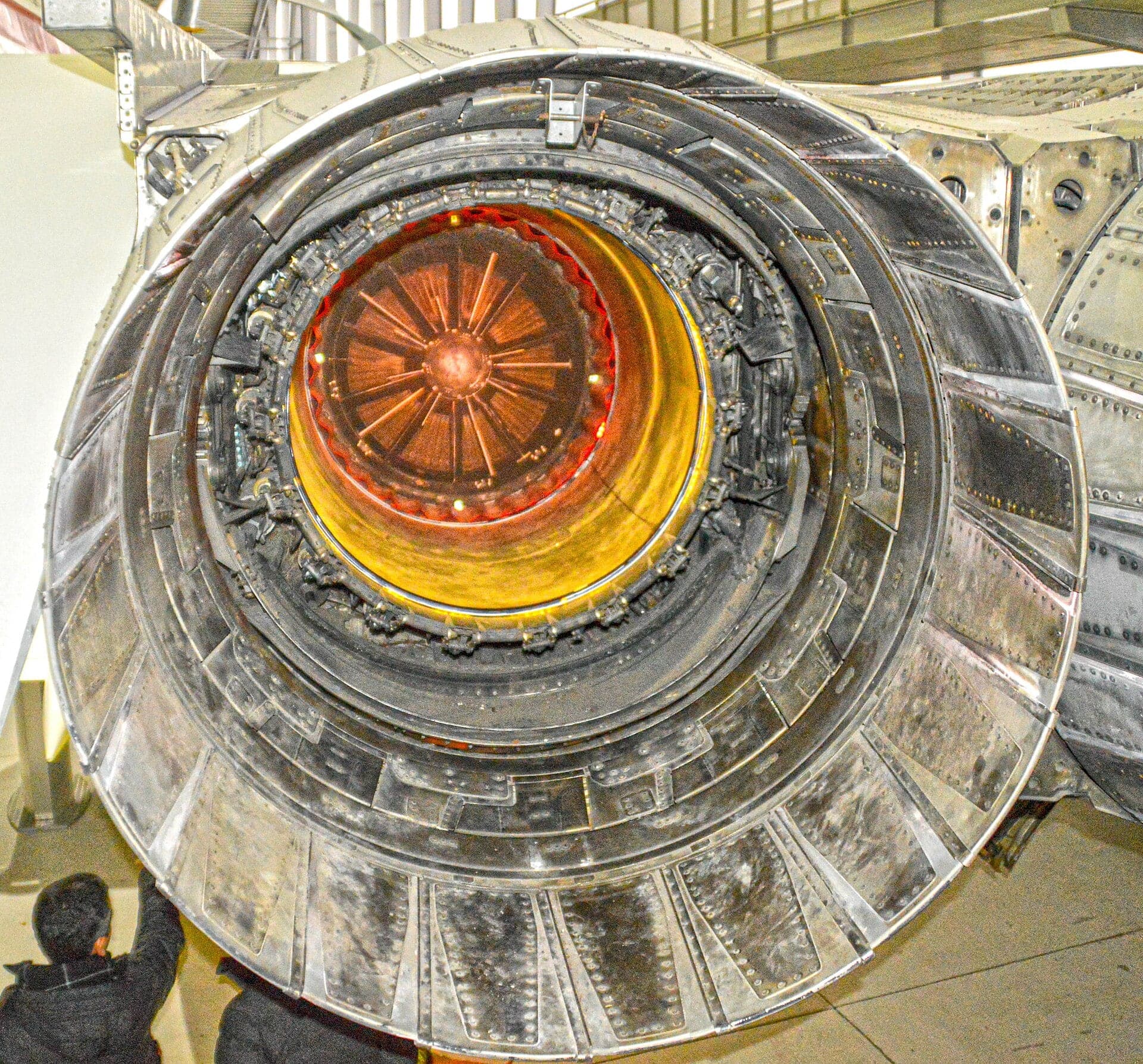
The engine left no direct descendant. The Mk 622 and the Concorde “B” were abandoned in the 1970s, and no supersonic airliner followed. Its lessons lasted longer: the idea that at supersonic speed intake, engine and nozzle form a single propulsion system; early digital intake control and data buses; and, less happily, the demonstration that a supersonic airliner's future would be decided as much by noise as by speed.
The wider Olympus family also outlived its most famous member, continuing in service as marine and industrial gas turbines long after the last Concorde landed.
Output by altitude
A piston engine has no single power figure. Each rating below is what the sources publish for one mark under one set of conditions, at the altitude it was measured at.
| Mark and conditions | Altitude | Output |
|---|---|---|
| Olympus 593, original design, dryMaximum thrust without reheat (published rating) | Sea level | 89kN |
| Olympus 593, original design, with reheatMaximum take-off thrust with reheat (published rating) | Sea level | 136kN |
| Olympus 593-22R (prototypes), dryMaximum thrust without reheat (published rating) | Sea level | 154kN |
| Olympus 593-22R (prototypes), with reheatMaximum take-off thrust with reheat (published rating) | Sea level | 165kN |
| Olympus 593 Mk 610 (Jane's), dryMaximum thrust without reheat (published rating) | Sea level | 139.4kN |
| Olympus 593-610-14-28, dryMaximum thrust without reheat (published rating) | Sea level | 142kN |
| Olympus 593 Mk 610 (Jane's), with reheatMaximum take-off thrust with reheat (published rating) | Sea level | 169.2kN |
| Olympus 593-610-14-28, with reheatMaximum take-off thrust with reheat (published rating) | Sea level | 169kN |
Mark evolution
Olympus 593D
1964Two derivative engines, close to the TSR-2's Olympus 22R, completed in July 1964.
To prove turbine cooling and sustained high-temperature running.
Showed the engine was too small for the grown Concorde.
A prototype-standard Olympus 593 on display at the National Museum of Flight, East Fortune, Scotland Olympus 593B
1965The enlarged redesign (“B” for big), first run in November 1965; the letter was later dropped.
Olympus 593-22R
165 kNPowerplant of the Concorde prototypes, uprated as the aircraft specification changed.
- Olympus 593-602B
An Olympus 593-602B on a yellow stand in the Whittle Building at Cranfield University Olympus 593-602
An intermediate build standard before the production Mk 610; a 602B survives at Cranfield University.
- Olympus 593 Mk 610
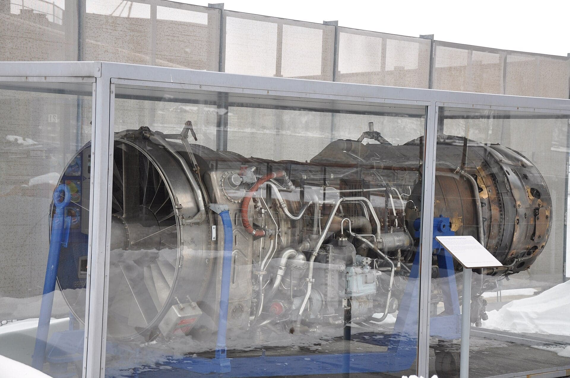
A complete Rolls-Royce/Snecma Olympus 593 Mk 610 on its transport stand at Aerospace Bristol, seen from the front quarter with its compressor intake, casings and pipework exposed The four Olympus 593 engines of Air France Concorde F-BVFB on red stands at the Technik Museum Sinsheim Olympus 593 Mk 610-14-28
1976169 kNThe production engine flown by Air France and British Airways from 1976 to 2003.
Olympus 593 Mk 622
Proposed quieter, higher-thrust version without reheat for the Concorde “B”; not built.
- Accident survenu le 25 juillet 2000 au lieu-dit La Patte d'Oie de Gonesse (95) au Concorde immatriculé F-BTSC exploité par Air France — rapport final, Bureau d'Enquêtes et d'Analyses pour la sécurité de l'aviation civile (BEA)
- Accident to the Concorde registered F-BTSC operated by Air France on 25 July 2000 at Gonesse, Bureau d'Enquêtes et d'Analyses (BEA)
- Rolls-Royce Olympus 593 Mark 3B aero-engine, c 1969, Science Museum Group Collection
- Concorde Olympus 593 Mk 610 engines, Heritage Concorde
- Concorde retirement 2003, Heritage Concorde
- Rolls-Royce Engines: Olympus, Grace's Guide to British Industrial History
- Rolls-Royce/Snecma Olympus 593, Wikipedia
- Rolls-Royce Olympus, Wikipedia
- Concorde, Wikipedia
Checked September 15, 2026